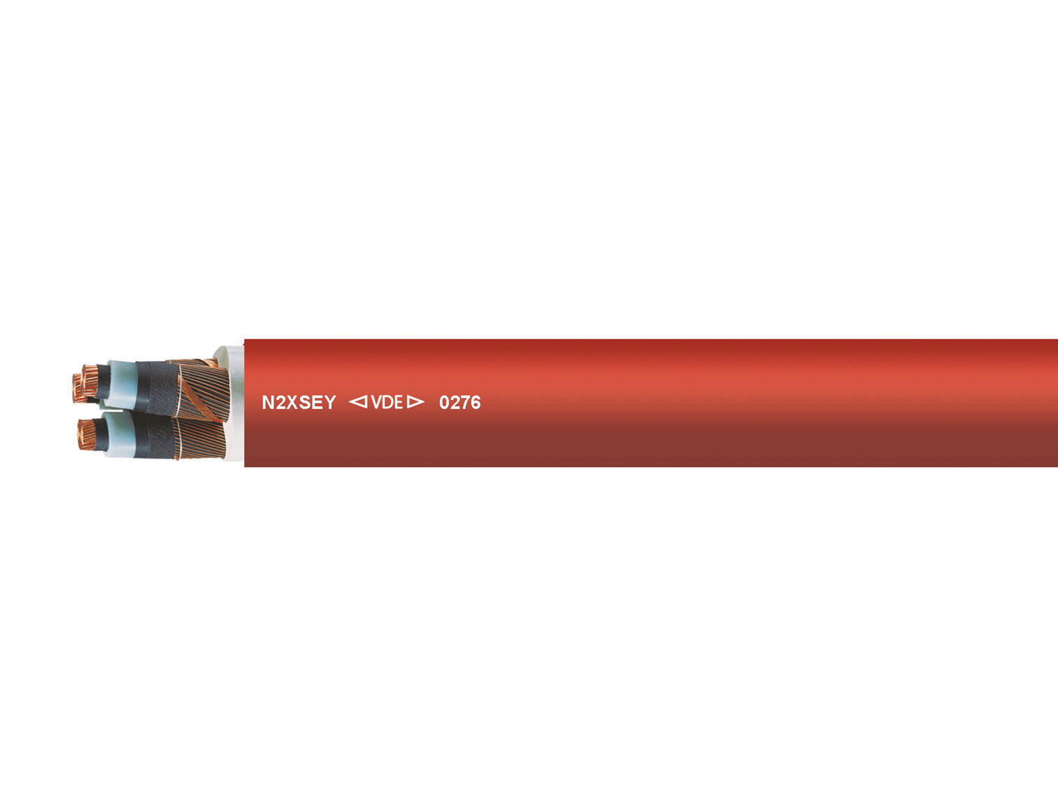

N2XSEY red 3 x 185 rm mm²
Part No. 34346
Item Details N2XSEY red 3 x 185 rm mm²
- Part No.
- 34346
- Item description
- N2XSEY red 3 x 185 rm mm²
- Outer Ø mm (approx.)
- 68
- AWG (approx.)
- 350 kcmil
- Cu factor per km
- 5645.0
- Weight kg/km (approx.)
- 9200.0
- Copper base in EUR / 100 kg
- 0
- Metres per Packaging Unit
- 500, 1000
- Cut-to-length service available
- yes
- EAN / GTIN
- 4060892277092
- Customs tariff number
- 85446010
Technical Data N2XSEY red 3 x 185 rm mm²
| Medium voltage cable acc. to DIN VDE 0276, IEC 60502 | |
| Temperature range | during installation -5°C |
| Permissible operating temperature of the conductor | +90°C |
| Nominal voltage | AC U0/U 6000/10000 V |
| Max. permissible operating voltage | three-phase alternating current (AC) conductor/conductor 12000 V |
| Test voltage core/core | 15000 V |
| Minimum bending radius | 15x Outer-Ø |
Details N2XSEY red 3 x 185 rm mm²
Cable Structure
-
- Copper conductor bare, stranded acc. to DIN VDE 0295 Class 2 / IEC 60228 Class 2
-
- Inner conductive layer
-
- Core insulation: XLPE
-
- Outer conductive layer
-
- Cores stranded
-
- Zwickelfüllung
-
- Screen: braiding of copper wires with one or two counter helix conductors
-
- Outer sheath: PVC acc. to HD 620 S2 (compound type DMV6)
-
- Sheath colour: red
Properties
-
- the materials used during manufacturing are cadmium-free, contain no silicone and are free from substances harmful to the wetting properties of lacquers
Tests
-
- flame-retardant acc. to DIN VDE 0482-332-1-2 / DIN EN 60332-1-2 / IEC 60332-1-2
Notes
-
- rm = round, stranded conductor
-
- the conductor is metrically (mm²) constructed, AWG numbers are approximated, and are for reference only
-
- for maximum operational reliability, the core insulation and the outer conductive layer are simultaneously extruded and permanently welded together. For installation, a peeling tool is recommended.
Application
-
- In Innenräumen und in Kabelkanälen, im Freien bei geschützter Verlegung sowie auf Pritschen für Industrie- und Schaltanlagen und Kraftwerke. Eingeschränkte Verwendung bei Verlegung in Erde, wenn der PVC-Außenmantel infolge starker mechanischer Beanspruchung beschädigt werden kann. Durch die innere Leitschicht zwischen Leiter und VPE-Isolierung und der festhaftenden äußeren Leitschicht auf der VPE-Isolierung wird ein teilentladungsfreier Aufbau mit hoher Betriebssicherheit gewährleistet.
